Essay
What a Bag of Brass Inserts Taught Me About Parametric CAD
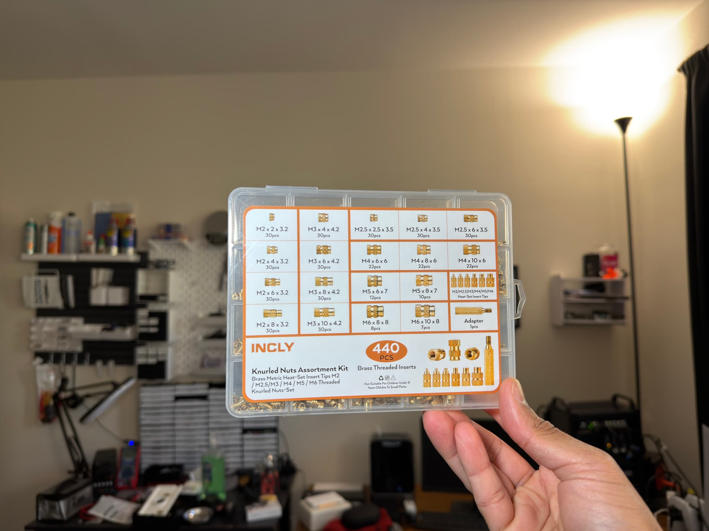
A few weeks ago I bought a 440-piece assortment kit of brass heat-set inserts off Amazon. You know the ones: a plastic organizer box with a dozen compartments, each holding 30-something of these tiny knurled brass cylinders in sizes from M2×2×3.2 up to M6×10×8. I needed them for OffGrid Devices, my little hardware side project where I design and sell MagSafe-compatible enclosures for Meshtastic and MeshCore mesh networking devices. The enclosures are 3D printed in PETG, and the inserts give them real metal threads for the M-screws that hold everything together.
I already knew how to use them. What I didn't know, and what I thought would be a quick afternoon project, was how to model one in CAD so I could drop it into my enclosure files and see exactly how it sits in the print.
Turns out, a brass insert is way more complicated than it looks. Here's what I learned over the course of about two days of false starts, geometric confusion, and one very frustrated evening where I was convinced Shapr3D was broken. It wasn't. I was.
The first surprise: these things are not cylinders
My first attempt was a smooth cylinder with a hole in it. Ten seconds of work. Done, right?
Then I actually looked at one up close.
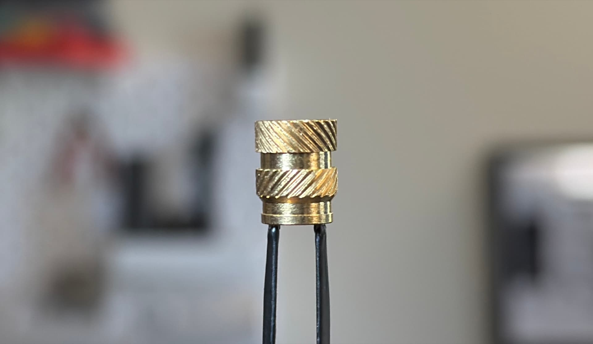
A real heat-set insert has at least five distinct zones stacked along its length:
- A pilot lower section at the very bottom with a small locating lip that flares out slightly
- A pilot upper section that necks in just above it
- A lower knurl band with diagonal grooves running one way
- A necked gap between the two knurl bands
- An upper knurl band with diagonal grooves running the opposite way
Every one of these features has a reason. The two opposing knurl directions give the insert both pull-out resistance and torque-out resistance when it's melted into plastic: one direction keeps it from being yanked out, the other keeps it from spinning when you drive a screw into it. The necked gap lets molten plastic flow into it during installation and mechanically lock the insert in place. The pilot lip at the tip is a locating shoulder that helps the insert self-align as it enters the printed hole.

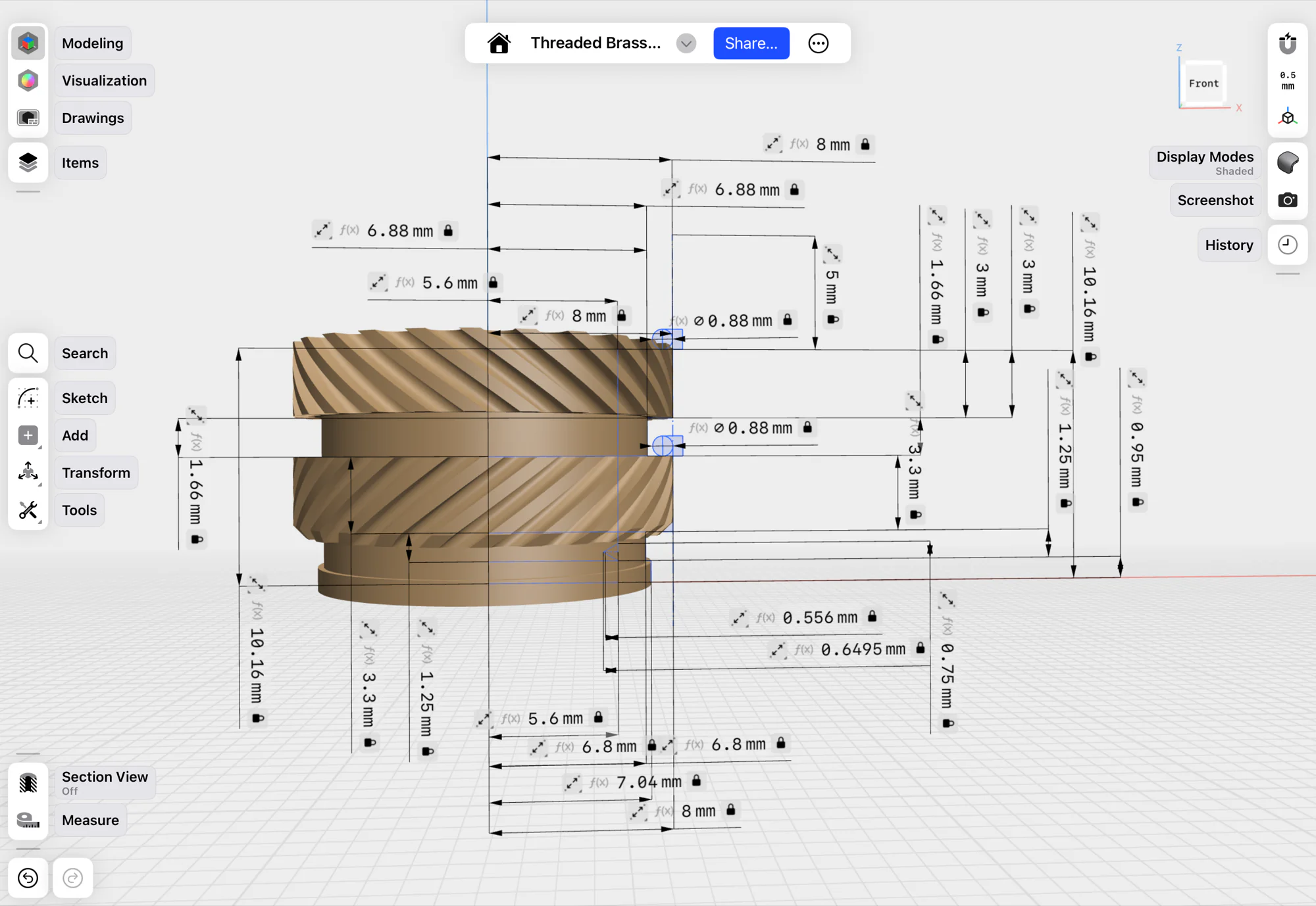
I measured one of my M6×10×8 inserts with calipers and wrote down all ten dimensions: five lengths and five diameters. Then I tried to figure out the ratios, because I didn't just want to model one size. I wanted one master file that could generate any size I owned by typing in three numbers.
Ratios are your friend
The length ratios turned out to be consistent across sizes. The pilot is always about 22% of the total length, split between the locating lip and the necked-in upper portion. The two knurl bands are about 30–33% each. The gap is about 16%. Same story on the radial side: the gap necks down to about 86% of the outer radius, the pilot upper narrows further to 83%, and the pilot lip flares out to 88%.
One small thing I had to be careful about: Shapr3D's revolve tool spins a 2D profile around an axis, which means every radial value in the sketch is a radius, not a diameter. So even though the inserts are spec'd by outer diameter (the "3.2" in "M2×2×3.2"), everything in the model has to be halved first. I set up a single derived variable called outerRadius = outerDiameter_changeMe / 2 and made every radial ratio read from that: gapRadius = outerRadius × 0.86, and so on. Naming them ...Radius keeps the semantics honest — if they were called ...Diameter but held half-sized values, every downstream math operation would be a loaded gun.
This was all beautiful, right up until I tried to model the internal threads.
You don't actually need real threads
Here's something nobody tells you when you start CAD: most vendors don't model functional threads inside their published part files. CNC Kitchen, ruthex, McMaster-Carr: none of their public CAD files for heat-set inserts have real helical threads inside the bore. They're just smooth holes.
Why? Because the actual brass inserts you're buying have real threads already. The CAD model is just a visual representation. When I drop it into my enclosure design, the point is to see how much space it takes up, where the pocket should go in my 3D print, and how the screw enters from the other side. The screw goes into the real brass insert when you assemble the physical part, not the CAD one.
Modeling real threads is expensive. They slow down the file, they make the mesh noisy, and they add zero functional value. The professional move is to leave the bore as a smooth cylinder at the tap drill diameter.
I decided to model them anyway, because I wanted to learn. And I'm glad I did, because this is where the real lessons started.
The 60° angle trap
ISO metric screw threads have a 60° flank angle. Everyone knows this. It's in every textbook. So I drew a triangle with base equal to pitch × 0.75 and depth equal to pitch × 0.5413, which I'd looked up as the "working thread depth," hit measure the apex angle, and...
69.4266°.

I sat there staring at it. The math looked right. The formulas were the ones CAD tutorials use. But the geometry was wrong.
Here's the trap: depth = 0.5413 × pitch is the truncated working depth, which assumes the triangle has a flat apex, making it a trapezoid, not a sharp point. If you use the truncated depth value on a sharp triangle, you've changed the geometry without knowing it, and the angle widens. For a sharp 60° triangle with a base of pitch, you actually need a depth of 0.866 × pitch. That's √3/2, the full height of an equilateral triangle.
I had two choices: use a proper trapezoid with the flat apex (ISO-accurate), or keep a simplified sharp profile and make sure the geometry stayed internally consistent. For a visual-only CAD model either is fine. I ended up keeping the simpler profile, but only after making the depth and base width agree with each other so the angle stayed at 60°.
The lesson: when you pull a formula off the internet, know what geometric assumption it was written for. 0.5413 and 0.866 aren't interchangeable. They describe different triangles.

The parametric workaround I was told wouldn't work
Shapr3D's variable system is great. You define inputs like length_changeMe, outerDiameter_changeMe, threadSize_changeMe and everything else flows from formulas. The _changeMe suffix is a deliberate UX hint: when you open the Variables panel and see 25 rows, it's instantly obvious which three you're allowed to touch. Change one of those three numbers, the whole model updates.
The one thing Shapr3D doesn't support is conditional logic. There's no if threadSize_changeMe == 6 then pitch = 1.0. No if-statements, no lookup tables, no switch expressions. Just arithmetic.
This was a problem, because ISO metric pitch isn't a clean formula. It's a lookup table:
| M-size | Pitch (mm) |
|---|---|
| M2 | 0.40 |
| M2.5 | 0.45 |
| M3 | 0.50 |
| M4 | 0.70 |
| M5 | 0.80 |
| M6 | 1.00 |
You can't compute pitch from thread size with any simple equation. The relationship between them is all over the place.
But I found a workaround using sign() and abs(). The expression 1 - sign(abs(x - target)) evaluates to 1 when x equals target, and 0 otherwise. Chain six of those together, multiply each by the corresponding pitch value, and sum them. You've just built a lookup table out of pure math.
Here's the actual formula pasted verbatim from my file:
pitch = (0.4 * (1 - sign(abs(threadSize_changeMe - 2 mm)))
       + 0.45 * (1 - sign(abs(threadSize_changeMe - 2.5 mm)))
       + 0.5 * (1 - sign(abs(threadSize_changeMe - 3 mm)))
       + 0.7 * (1 - sign(abs(threadSize_changeMe - 4 mm)))
       + 0.8 * (1 - sign(abs(threadSize_changeMe - 5 mm)))
       + 1 * (1 - sign(abs(threadSize_changeMe - 6 mm)))) mm
It's ugly. I love it. It means I only ever type one number to set the thread size, and the pitch updates automatically across the entire model.
The same min(a, b) = (a + b − |a − b|) / 2 identity ended up showing up in two other places too — capping the groove diameter so it never exceeds 80% of the gap length, and capping the groove angle so extreme aspect ratios don't spiral out (more on that in a bit). It's become my favorite trick in a variable system without if-statements.
The thread touching problem
The next wall I hit: when the revolve angle was exactly 360° per pitch, which is what ISO specifies, the triangular thread profiles tried to touch each other at their corners, and Shapr3D threw an error.
The fix was obvious once I understood it: a real ISO thread isn't a pure triangle. It has small crest flats between adjacent threads. In geometry terms, that means the triangle base has to be smaller than one full pitch period, leaving a tiny gap at the top and bottom of each turn. I changed baseWidth to pitch × 0.75 and updated threadDepth to baseWidth × 0.866, keeping the 60° angle intact, and the error went away.
Another lesson: when a CAD tool throws a weird error, it's usually telling you the real geometry has a subtle constraint that your simplified version doesn't respect. The error isn't the bug. The simplification is.

One angle doesn't fit all
The threads were done. I turned my attention to the knurls — the diagonal grooves that give the insert its grip once it's melted into plastic.
The approach is straightforward on paper: sketch a small circle on the outer surface, revolve it a few degrees along a short helical path, and you get a single diagonal groove. Then circular-pattern it around the insert's axis and you've got a whole band. Flip the helix direction for the second band so the grooves run the opposite way.
On the M6×10×8 I'd been modeling, a 45° revolve angle looked exactly right. So I used 45 deg everywhere and moved on.
Then I started plugging in other sizes, and the grooves stopped reading as knurls. On short, fat inserts like M2×2×3.2, the grooves were way too steep — they looked almost vertical. On long, thin inserts like M6×10×8 itself, they were fine, because that's what I'd calibrated against. The problem wasn't the angle I'd picked. It was that the right angle depends on the shape of the insert. A square-ish body wants a gentler helix than a tall skinny one, because the helix has less circumference to wrap around before it runs out of band length.
The fix was to make the angle a function of the aspect ratio:
grooveAngleRaw = length_changeMe / outerDiameter_changeMe * 60 deg
grooveAngleMax = 100 deg
grooveAngle    = (grooveAngleRaw + grooveAngleMax
                  - abs(grooveAngleRaw - grooveAngleMax)) / 2
The first line says: the groove angle is proportional to how tall the insert is relative to its width. I calibrated the 60 deg multiplier so that a perfectly square insert (length = OD, ratio = 1.0) gets 60° grooves, and everything else scales from there. The M4×6×6 and M6×8×8 land at exactly 60° — which looks right — and the old M6×10×8 baseline comes out to 75°, which also looks right.
The second and third lines cap the result at 100° using the same min() identity from the pitch formula. Without the cap, an M2×8×3.2 (ratio = 2.5) computes to grooveAngleRaw = 150°, which wraps the groove so far around the insert that it reverses direction and produces garbage. Six of the eighteen sizes hit the cap — all the tallest variants of the smallest-OD inserts — and the cap just keeps them at a reasonable steep-but-sane 100°.
Here's what ends up happening across the library:
| Insert | L ÷ OD | grooveAngle |
|---|---|---|
| M2×2×3.2 | 0.63 | 37.5° |
| M3×4×4.2 | 0.95 | 57.1° |
| M4×6×6 | 1.00 | 60.0° |
| M6×10×8 | 1.25 | 75.0° |
| M3×8×4.2 | 1.90 | 100.0° (capped) |
| M2×8×3.2 | 2.50 | 100.0° (capped) |
Same formula, eighteen different visually appropriate results. This is the moment parametric design starts paying for itself — you pick the hard numbers once (60, 100), and they propagate everywhere.
What I ended up with
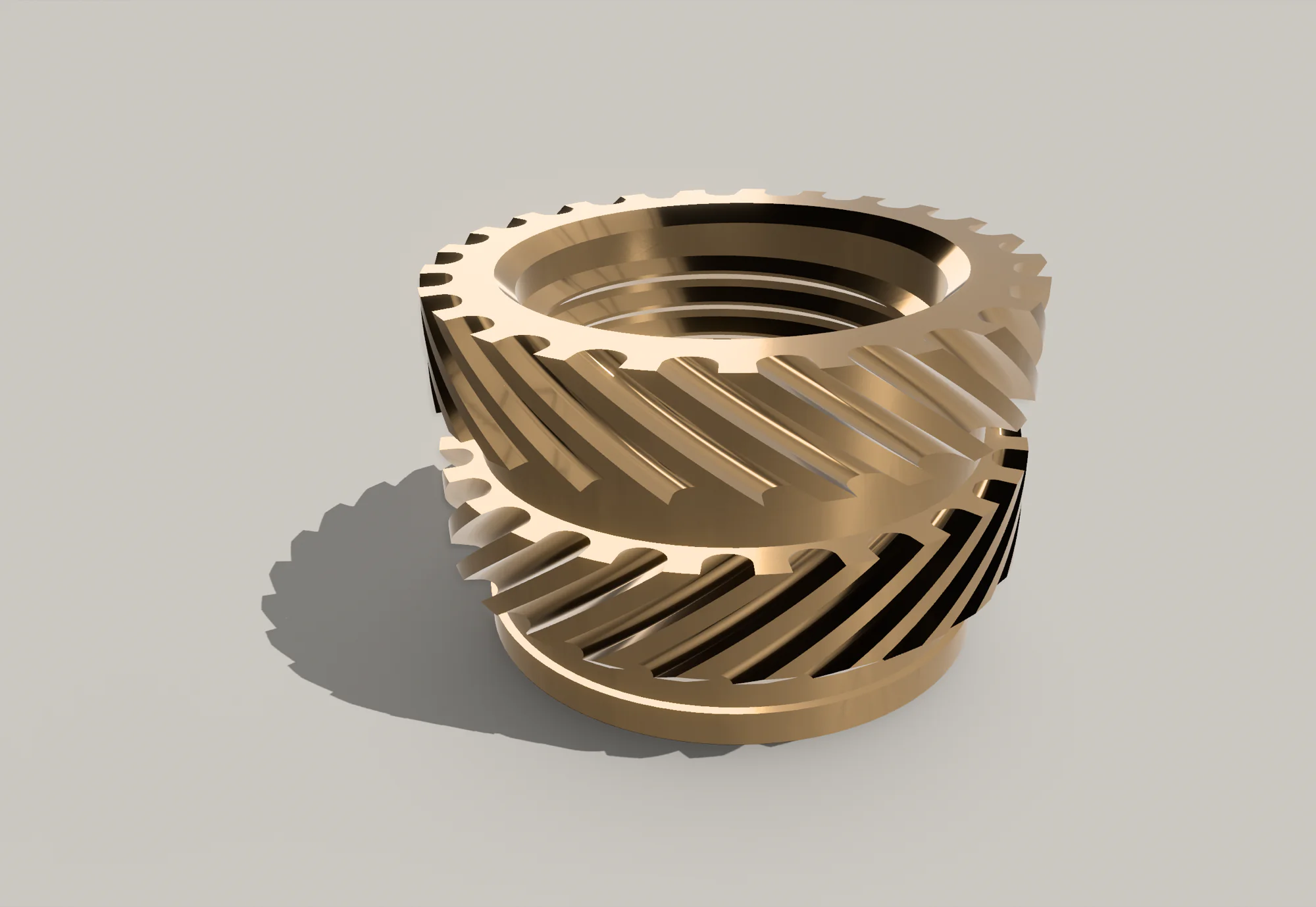
One Shapr3D file with three input variables — threadSize_changeMe, length_changeMe, outerDiameter_changeMe — plus pitch, which is auto-computed from the first one. Every length and every radius of every zone is derived. I can model any size from M2×2×3.2 up to M6×10×8 by changing three numbers and hitting enter. Eighteen sizes from one master file.
The file includes modeled knurls (with angle-scaling), internal threads, the stepped pilot geometry, and pitch-scaled chamfers, all driven from the same variable set. Change the three main dimensions and the whole insert updates cleanly. Everything just works.
If you want to study or adapt the file yourself, I also wrote a complete technical reference doc covering the variables, formulas, pitch lookup, and current limitations. The published Shapr3D master file and exports are on Printables and GrabCAD.
Other brass inserts exist (and they're different)
The inserts I modeled are the "double-knurled" style: two opposing helical knurl bands with a smooth gap in the middle. These are by far the most common type sold for 3D printing, and they're what you'll find in every budget assortment kit on Amazon. But there are other types worth knowing about:
- Tapered inserts (McMaster-Carr style): a single conical body with fine knurling. Designed to self-center as they sink in. More forgiving of hole diameter variation.
- Straight knurled inserts (RS Pro, some CNC Kitchen variants): a single knurled band, no gap. Simpler geometry but less torque-out resistance.
- Press-fit inserts: no heat required. You just press them into an oversized hole. Work best in rigid materials.
- Ultrasonic inserts: installed with ultrasonic welders instead of soldering irons. Industrial process, not really for hobbyists.
My parametric file only covers the double-knurled style. If you need one of the others, the proportional approach I used should still work. You'd just adjust the ratios based on measuring your specific inserts with calipers. The technical doc covers the variable structure, pitch lookup, and the current model limits if you want to adapt it.
What I'd tell someone else thinking about trying this
Honestly? If you'd shown me a picture of my final variable panel on day one, 25+ variables and half of them driven by formulas referencing other formulas, I would have closed the tab. It looks impossible.
But here's the thing: every one of those variables got added one at a time, in response to a specific problem I was trying to solve. I didn't sit down and plan the whole thing up front. The model just got more explicit each time the geometry forced me to clarify another relationship. Each addition took maybe 20–30 minutes of fiddling, most of which was staring at something broken and slowly understanding why.
If you're trying to model something similar, and it doesn't even have to be brass inserts, here's what helped me most:
Measure the real thing with calipers first. I wasted time early on trying to work from product listings and Amazon descriptions. The actual part in your hand has information no spec sheet captures. Measure it, write the numbers down, and don't trust anything until you've verified it physically.
Work in ratios, not absolute values. The moment I wrote lowerKnurlLength = length_changeMe × 0.33 instead of lowerKnurlLength = 3.3 mm, the model became reusable. One formula, eighteen sizes. That's the whole point of parametric design.
Name variables for what they are, not what they look like. A radius should be called a radius, not a diameter. A raw intermediate value should read as intermediate. Good names make wrong math visible; bad names hide it.
When a CAD error is confusing, the geometry probably has a subtlety you're missing. Don't fight the error. Read it, believe it, and go figure out what real-world constraint it's pointing at. It's almost always right.
It's okay to make visual-only simplifications, but know which ones you're making. I could have skipped the internal threads entirely and nobody would have noticed. I chose to include them anyway because I wanted to understand how they work. That's a legitimate reason. "It matters for the screw to function" is not.
If one parameter only looks right at one size, make it a function of the inputs. My first pass used a hardcoded 45° groove angle. It looked great on the insert I calibrated against and weird on everything else. The fix was to let the angle scale with the insert's aspect ratio. Hardcoded constants are almost always calibrated to the thing you're currently staring at.
Use AI as a sparring partner. I talked through most of this project with Claude, not to have it build the model for me, but to have someone to bounce geometry questions off of. "Why is my apex angle 69° when it should be 60°?" is a question that would take me an hour to Google and ten seconds to get a useful answer to in a chat. The answer is only useful if you can evaluate it, so you're still doing the thinking, but the feedback loop is dramatically faster than forum-hunting.
Expect frustration. Keep going anyway. At one point I was convinced my entire approach was wrong and I should start over. I didn't start over. I found the one wrong formula, fixed it, and moved on. Most CAD frustration is one wrong formula away from working.
Resources
- Technical Documentation — Full variable reference, formulas, pitch lookup, and design notes
- Printables — Master Shapr3D file and all size exports
- GrabCAD — Individual STEP/STL files for 18 sizes
- 440-piece INCLY brass insert kit on Amazon — the exact kit I measured for this library (affiliate link)
- OffGrid Devices — More hardware project work
As an Amazon Associate, I earn from qualifying purchases.